MEAN WELL DRC-40 Series 40W DIN Rail Power Supply with Battery Charger | DRC-40A / DRC-40B
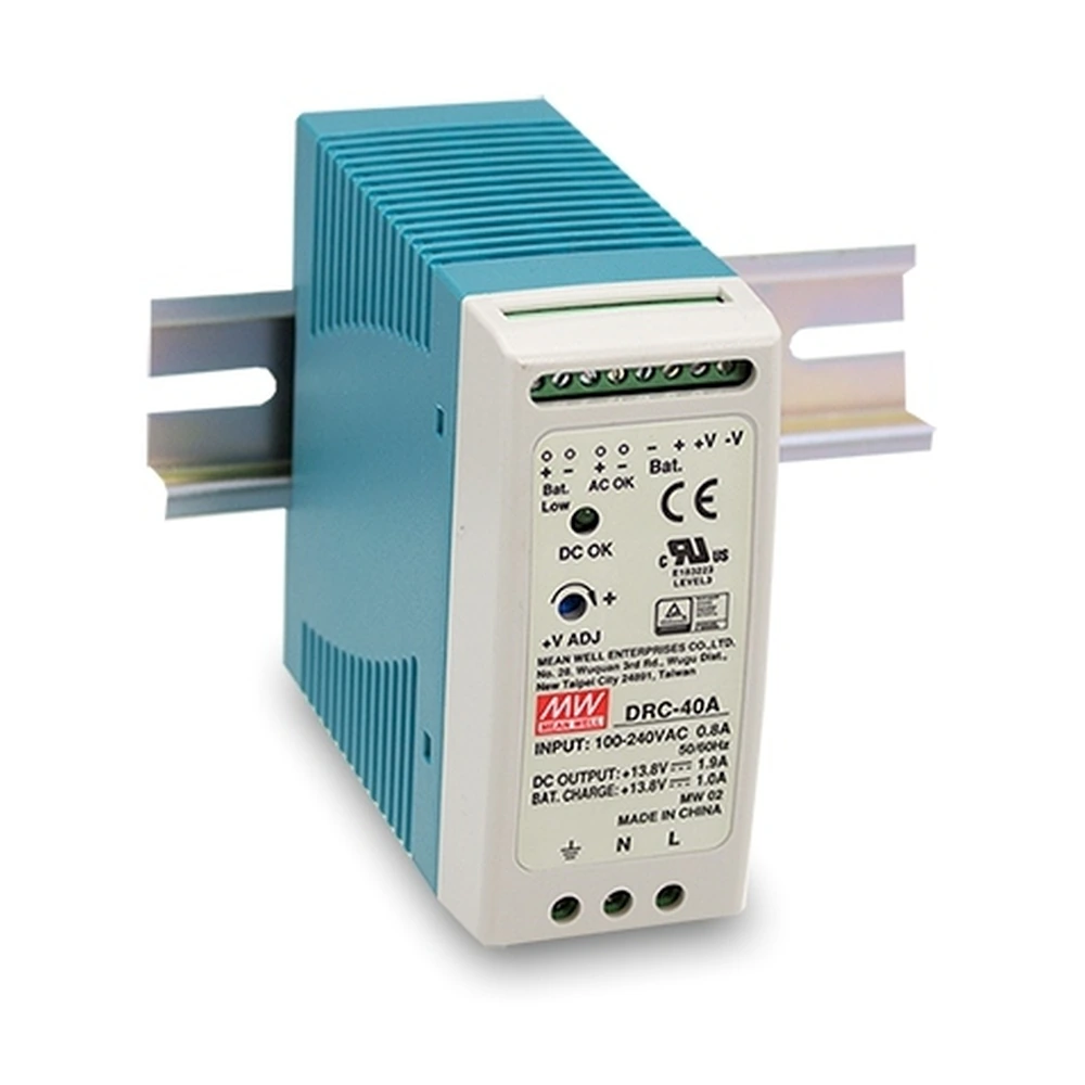
The MEAN WELL DRC-40 Series is a compact 40W DIN rail AC/DC power supply with battery charger and UPS function, designed for security systems, access control, alarm systems, emergency lighting, central monitoring systems and other applications requiring reliable DC power with battery backup.
It accepts a universal 90–264VAC input and also supports 127–370VDC input. The series includes DRC-40A with 13.8VDC output for 12V battery systems and DRC-40B with 27.6VDC output for 24V battery systems, providing up to 40.02W rated power in a compact DIN rail package.
In addition to the main DC output, the DRC-40 Series provides a dedicated battery charger output and automatically supports backup operation when AC mains power is interrupted. Built-in protection functions include short circuit, overload, overvoltage, battery low cut-off and battery reverse polarity protection by fuse.
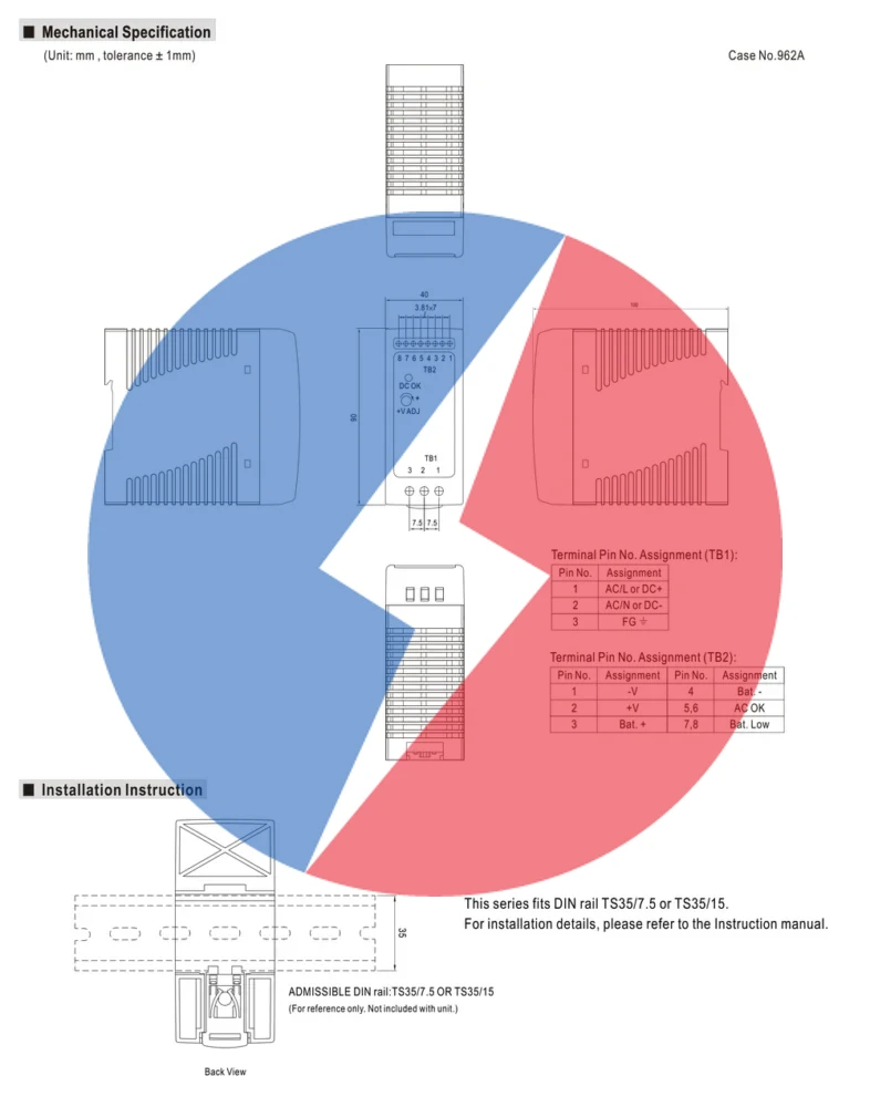
For system monitoring, the DRC-40 Series provides AC OK and Battery Low alarm signals through TTL open collector outputs on standard models, with relay contact output available as an option. The power supply can be installed on TS35/7.5 or TS35/15 DIN rail and operates with free-air convection cooling.
Available models include MEAN WELL DRC-40A and MEAN WELL DRC-40B, covering 12V and 24V battery backup architectures for industrial security, access control and DC UPS applications.
It accepts a universal 90–264VAC input and also supports 127–370VDC input. The series includes DRC-40A with 13.8VDC output for 12V battery systems and DRC-40B with 27.6VDC output for 24V battery systems, providing up to 40.02W rated power in a compact DIN rail package.
In addition to the main DC output, the DRC-40 Series provides a dedicated battery charger output and automatically supports backup operation when AC mains power is interrupted. Built-in protection functions include short circuit, overload, overvoltage, battery low cut-off and battery reverse polarity protection by fuse.
For system monitoring, the DRC-40 Series provides AC OK and Battery Low alarm signals through TTL open collector outputs on standard models, with relay contact output available as an option. The power supply can be installed on TS35/7.5 or TS35/15 DIN rail and operates with free-air convection cooling.
Available models include MEAN WELL DRC-40A and MEAN WELL DRC-40B, covering 12V and 24V battery backup architectures for industrial security, access control and DC UPS applications.